
First off let me state that I am by no means a certified mechanic nor do I recommend anyone completing the following process if they are unsure they are capable. This document was created to document the procedure I took to rebuilt the top end of a 2000 KTM 300MXC. Use the information contained within at your own risk.
|
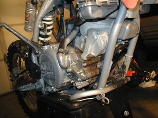
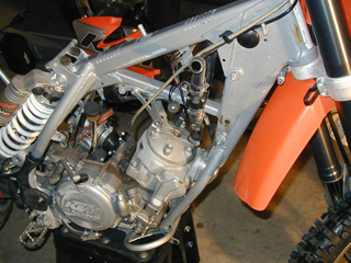
I started by thoroughly cleaning the bike while fully assembled. Once it was dried off I began disassembly. I removed all external parts to gain easy access to the engine. In this picture notice the sub frame and exhaust pipe has been removed. |
|
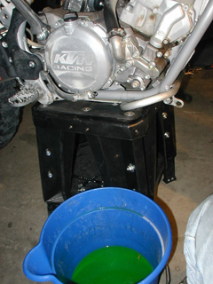
Drained the coolant. |
| |
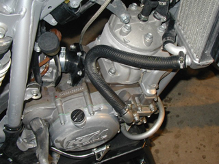
With a little more access gained from the removal of the exhaust pipe I was able to get things a little cleaner. |
|
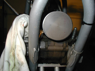
Ready to proceed with removing the cooling system as things are looking nice and clean. |
|
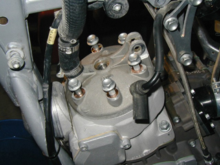
Cooling system removed, including the radiators and hoses. Also loosened up the top engine mount to the frame and removed the spark plug. |
|
Loosened the cylinder head bolts. Watch out for those copper washers. |
|
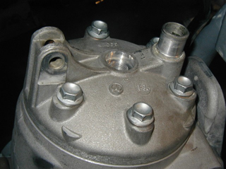
Removed the cylinder head. |
|
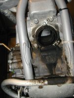
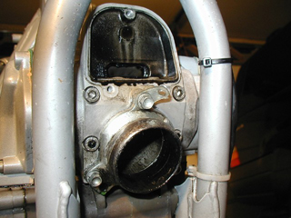
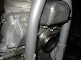
Removed the power valve exhaust cover. This must be done to gain access when removing the cylinder from the base. |
|
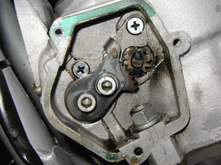
There were 3 bolts holding the right side power valve cover on. The long bolt goes on the bottom. Once the bolts were removed just had to pull the cover straight off. |
|
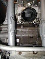
Once the cover was off, made sure to cover the hole into the bottom that the power valve actuator came through. Wouldn't want anything falling into that hole! |
|
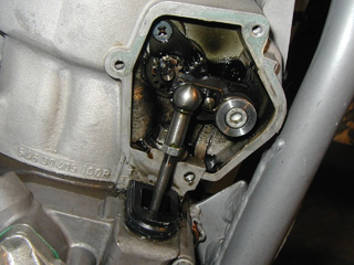
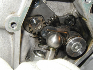
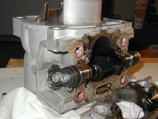
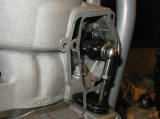
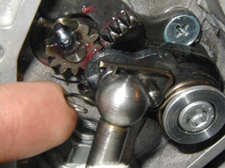
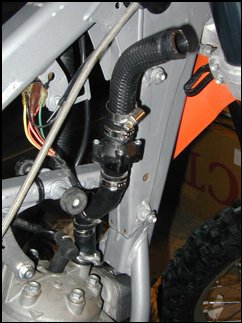
Good close up of the power valve (PV) actuator and how it is connected. Notice the little clip below the ball, that is what must be removed in order to allow the PV actuator arm to be pulled from the PV assemble on the cylinder. |
|
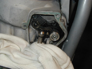
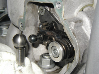
That clip just slides to the left, allowing it to be removed then by pulling it straight down. |
|
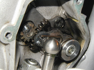
Just had to pull the actuator arm off the assembly so I could progress toward removing the cylinder. Notice I placed the clip back into it's correct position for storage while the cylinder was going to be removed. |
|
Then it was time to remove the cover from the other side of the cylinder. |
|
Using the closed end of my trusty 13mm wrench I loosened the nuts holding the cylinder on. I believe they were torqued to 25 ft/lbs. |
|
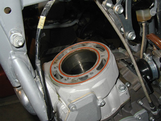
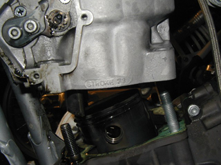
After removing all four bolts off comes the cylinder. Mine lifted right off the base with minimal effort. I have heard to use a rubber mallet and lightly tap the cylinder swinging with a upward angle if it is stuck. Never use a screwdriver or similar device to pry the cylinder from the base! Notice how the piston is down low in the stroke. I used the kick starter to get it in this position which made removing the cylinder easier. |
|
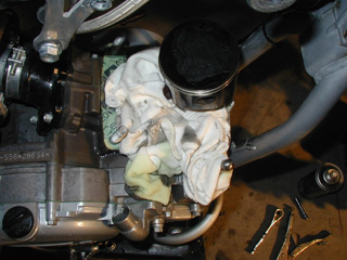
Stuff a rag in the crankcase hole to keep anything from falling into it. |
|
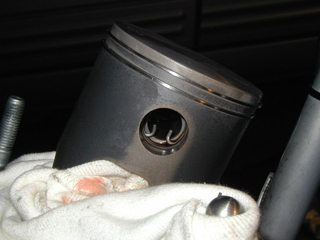
This is actually an after shot of the new piston installed, but notice the circlip in the hole on the piston. This was very simple to remove with some standard needle nose pliers. I removed both circlips then proceeded to remove the wristpin. |
|
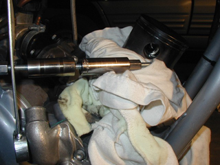
This is the "puller" device I created to remove the wristpin. It was made up of a 3/8th (maybe) deep socket, some 1/4" threaded rod, two coupler nuts, and my sparkplug wrench which had the hole in the handle. As I eventually found out there was one flaw with my design. I figured I would need something to hold against the piston as I tightened the nut and thereby shortening the rod to pull the wristpin out, thus the sparkplug wrench. Well I began to pull the wristpin out but when it butted up against the wrench it would go no farther. Perhaps putting a piece of PVC pipe, with the inside diameter wide enough to accept the wristpin, between the wrench and the piston would have allowed the wristpin to be removed by pulling it into the PVC pipe while tightening the nut. Bottom line was to remove the wristpin without putting any opposing force on the connecting rod. |
| |
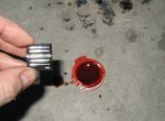
With the old piston, wristpin, and wristpin bearing removed it was time to install the new piston on the connecting rod. Before installing the wristpin bearing (left) and the wristpin (right) I coated each with plenty of 2-stroke oil. This is important because there is little lubrication for these pieces during engine operation. |
|
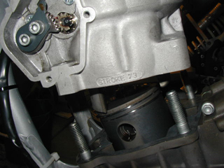
On the new piston there was an obvious arrow (not visible in this picture) pointing toward the exhaust side of the piston. When installing the new piston I made sure the arrow pointed toward the front of the bike. In this picture (taken from an angle of behind the front wheel) the arrow would be pointing down toward the ground. |
|
At this point is where I began the cleaning of the power valve parts. I found there to be plenty of carbon buildup on the parts and the cleaning process to be somewhat straightforward. It made the process take a little while longer, but to avoid the possibility of a stuck power valve now was a good time to complete the process. This is documented in the power valve article. |
|
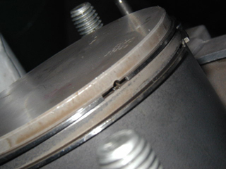
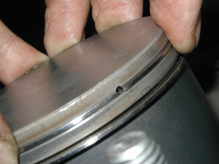
Here it is important to make sure the rings are in the proper position on the piston. Notice the ring end gap and the mark on the piston where the ring end gap should be located. If this is not set correctly during reinstallation expect to be replacing the top end again very shortly. |
|
Here I have compressed the rings with my fingers. This is necessary to get the cylinder back over the piston and rings. Unfortunately the angle I have compressed this ring will now allow me to install the cylinder as it will be sliding down over the top of the piston. Do notice how they lineup with the indication on the piston. |
|
While compressing the rings like above I slipped the cylinder down over the new piston. I took my time and was cautions not to have the rings slip out of their proper position. Having another person's assistance would have been helpful during this stage. Don't forget to put a new gasket on the base. I used the same thickness gasket and made sure to align it correctly. Using a thinner gasket will increase compression, a thicker gasket will decrease compression. |
|
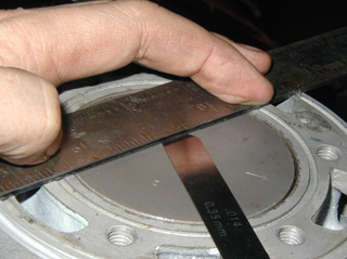
With the cylinder back in place, I gently cycled the kick starter a few times using my hands. Then I placed the piston at TDC (top dead center) and tightened down the cylinder nuts to 25 ft/lbs. Now it was time to take measurement "X" as according to the manual. |
|
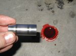
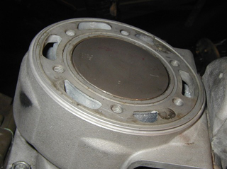
Using a straight edge or good rigid flat device I laid across the top cylinder and measured the clearance of the piston. Everything looked to be within specs so I proceeded. First I installed the new O rings into the grooves on the top of the cylinder. I had to stretch them a little and the note on the gasket kit said to coat them with Vaseline. |
|
Returned the cylinder cap to it's proper placement and tightened each bolt to 25 ft/lbs. Don't forget to install the support mount from the frame to the top of the cylinder also. |
|
A quick word of warning about reassembling the power valve actuator to the cylinder and the gasket for the cover. The only way to get the gasket on is to do it before attaching the power valve actuator arm to the power valve assembly. |
|
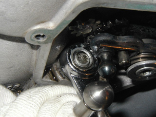
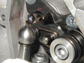
I removed the power valve clip from it's original location where I had stored it and pushed the power valve actuator arm onto the power valve assembly on the cylinder. |
|
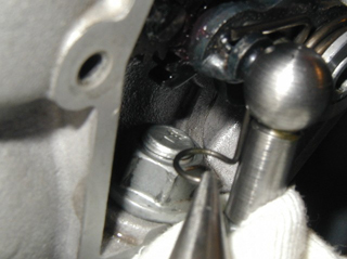
The needle nose pliers helped getting the clip back into the correct position. |
|
Then I just had to rotate it around and snap the clip into position to secure the actuator arm to the power valve assembly. |
|
Viola! |
|
Time to put on the power valve covers. |
|
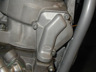
Then the power valve exhaust cover. |
|
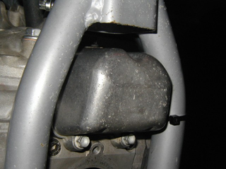
And finally the exhaust flange. |
|
Then reinstall the plumbing, fill the radiators with coolant, and reassemble the bike. I also changed the spark plug and the silencer packing. Now it is time to take it out and perform the break-in procedure. |
| Back to DesertMX Maintenance | |